

Sjors Krebbeks
-
Posts
744 -
Joined
-
Last visited
Content Type
Profiles
Case studies - Free
Case studies - Premium
Resources
Insider
Courses
Forums
Store
Everything posted by Sjors Krebbeks
-
 Dylan R. Hopkin is a renowned senior colorist working at one of Europes's leading post-production facilities - Nordisk Film Shortcut Oslo. He brings a wealth of color grading expertise to the table from numerous features films and TV dramas. In this masterclass he will focus on the "why's" of color grading, and discuss the artistic decisions behind shots and scenes. It will answer questions like where to place the highlight levels, how to avoid "fake" skin tones, decisions behind hues of elements in the scenes and how saturated images should be. About the instructor The instructor is Dylan R. Hopkin, is one of Scandinavias most sought after colorists and has colored an impressive list of European feature films and TV dramas. Additionally, he brings extensive experience as a color grading instructors as he has taught grading in several prestigious international film schoold and is a certified DaVinci Resolve trainer. Who is this course designed for? Colorists at all levels The Gradelab plugin mentioned (but not used) in the courses can be purchased at Ravengrade.com.
 -
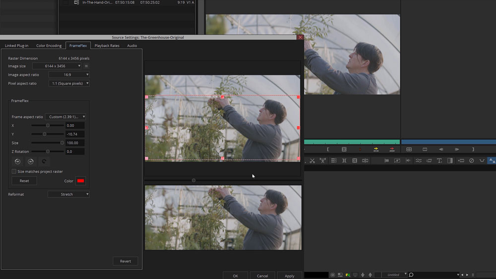 W elcome to our online Avid Media Composer Assistant Editor Training, led by renowned industry expert Kevin P. McAuliffe. If you're an aspiring assistant editor, or a filmmaker looking to strengthen your post-production skills this training is tailor-made for you. In this comprehensive course, we'll equip you with the necessary knowledge and techniques to excel as an assistant editor using Avid Media Composer. The training covers all essential aspects of assistant work, with a special focus on conform tasks, challenges and obstacles, and seamless round tripping with DaVinci Resolve. About the instructor Kevin P. McAuliffe is a renowned expert in post-production, specializing in Avid Media Composer and Davinci Resolve. With extensive experience, he's a sought-after instructor known for his clear teaching style and practical insight. Kevin is not only an instructor but also a working professional in industry forums, an active participant on conferences and events. Kevin's engagement with the larger editing community allows him to stay connected and continuously refine his understanding of the evolving editing landscape. Who is this course designed for? Avid Editors Aspiring Assistant Editors Post-production artists Lessons overview 01: Source settings and link setups 02: Frameflex and transcoding 03: Decompose, relinking and final transcoding 04: Grade before the LUT and utilizing camera frame rates 05: Creating dailies in DaVinci Resolve and Avid round-tripping 06: Various frame rates when round-tripping 07: List tool and creating spreadsheets with timeline information
 -
3D - A Beginners Guide to Stereoscopic Understanding
Sjors Krebbeks posted an insider Article in Workflow
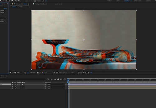 My interest in Stereoscopic imaging started in 2006. One of my close friends, Trevor Enoch, showed me a stereo-graph that was taken of him while out at Burning Man. I was blown away and immediately hooked. I spent the next four years experimenting with techniques to create the best, most comfortable, and immersive 3D I could. In 2007, I worked on Hannah Montana and Miley Cyrus: Best of Both Worlds Concert directed by Bruce Hendricks and shot by cameras provided by Pace. Jim Cameron and Vince Pace were already developing the capture systems for the first “Avatar” film. The challenge was that a software package had yet to be created to post stereo footage. To work around this limitation, Bill Schultz and I slaved two Quantel IQ machines to a Bufbox to control the two color correctors simultaneously. This solution was totally inelegant but it was enough to award us the job from Disney. Later during the production, Quantel came out with stereo support eliminating the need to color each eye on independent machines. We did what we had to in those early days. When I look back at that film, there is a lot that I would do differently now. It was truly the wild west of 3D post and we were writing the rules (and the code for the software) as we went. Over the next few pages I’m going to layout some basics of 3D stereo imaging. The goal is to have a working understanding of the process and technical jargon by the end. Hopefully I can help some other post professionals avoid a lot of the pitfalls and mistakes I made as we blazed the trail all those years ago. Camera 1, Camera 2 Stereopsis is the term that describes how we collect depth information from our surroundings using our sight. Most everyone is familiar with stereo sound; when two separate audio tracks are played simultaneously out of two different speakers. We can take that information in using both of our ears (binaural hearing) and create a reasonable approximation from the direction of where that sound is coming from in space. This approximation is calculated by the offset in time of the sound hitting one ear vs the other. Stereoscopic vision works much in the same way. Our eyes have a point of interest. When that point of interest is very far away our eyes are parallel to one another. As we focus on objects that are closer to us, our eyes converge. Do this simple experiment right now. Hold up your finger as far away from your face as you can. Now slowly bring that finger towards your nose, noting the angle of your eyes as you get closer to your face. Once your finger is about 3 inches away from your face, alternately close one eye and then the other. Notice the view as you alternate between your eyes, camera 1, camera 2, camera 1, camera 2. Your finger moves position from left to right. You also see “around” your finger more in one eye vs the other. This offset between your two eyes is how your brain makes sense of the 3D world around you. To capture this depth for films we need to recreate this system by utilizing two cameras roughly the same distance as your eyes. Camera Rigs The average interpupillary distance is 64mm. Since most feature grade cinema cameras are rather large, special rigs for aligning them together need to be employed. Side by side rigs are an option when your cameras are small, but when they are not you need to use a beam splitter configuration. Beam splitter rig in an "over" configuration. Essentially, a beam splitter rig uses a half silvered mirror to “split” the view into two. This allows the cameras to shoot at a much closer inter-axial distance than they would otherwise be able to using a parallel side by side rig. Both of these capture systems are for the practical shooting of 3D films. Image comes in from position 1. Passes through to camera at position 2. It is also reflected to the camera at position 3. You will need to flip it in post since the image is mirrored. Fortunately or unfortunately most 3D films today use a technique called Stereo Conversion, which is the process of transforming 2D ("flat") film to a 3D form. Conversion There are three main techniques for Stereo Conversion. Roto and Shift In this technique, characters and objects in the frame are roto’d out and placed in a 3D composite in virtual space. The scene is then re-photographed using a pair of virtual cameras. The down side to this is that the layers often lack volume and the overall effect feels like a grade school diorama. Projection For this method, the 2D shot is modeled in 3D space. Then, the original 2D video is projected onto the 3D models and re-photographed using a pair of virtual cameras. This yields very convincing stereo and looks great, but can be expensive to generate the assets needed to create complex scenes. Virtual World Stupid name, but I can’t really think of anything better. In this technique, scenes are created entirely in 3D programs like Maya or 3DS Max. As this is how most high end VFX are created for larger films, some of this work is already done. This is the best way to “create” stereo images since the volumes, depth and occlusions are mimicking the real world. The downside to this is that if your 2D VFX shot took a week to render in all of its ray traced glory, your extra “eye” will take the same. Cartesian Plane No matter how you acquire your stereo images, eventually you are going to take them into post production. In Post, I make sure the eyes are balanced for color between one another. I also “set depth” for comfort and to creatively promote the narrative. In order to set depth we will have to offset one eye against the other. Objects in space gain their depth from the relative offset in the other eye/view. In order to have a consistent language, we speak in number of pixels offset to describe this depth. When we discuss 2D images we use pixel values that are parallel with the screen. A given cordinate pair locates the pixel along the screens surface. Once we add the 3rd axis we need to think of a Cartesian plane laying down perpendicular to the screen. Positive numbers are receding away from the viewer into the screen. Negative numbers come off the screen towards the viewer. The two views are combined for the viewing system. The three major systems are Dolby, RealD, and Expand. There are others, but these are the most prevalent in theatrical exhibition. In Post we control the relative offset between the two views using a “HIT” or horizontal image transform. A very complicated way for saying we move one eye right or left along the X axis The value of the offset dictates where in space the object will appear. This rectangle is traveling from +3 pixels offset to -6 pixels offset. Often we will apply this move symmetrically to both eyes. In other words to achieve a -6 pixels offset, we may move both views -3 instead of one view moving -6. Using this offset we can begin to move comped elements or the entire “world” in Z space. This is called depth grading. Much like color, our goal is to try and make the picture feel consistent without big jumps in depth. Too many large jumps can cause eye strain and headaches. My first rule of depth grading is “do no harm.” Pain should be avoided at all costs. However, there is another aspect of depth grading beyond the technical side. Often we use depth to promote the narrative. For example, you may pull action forward to be more immersed in the chaos, or you can play quiet drama scenes at screen plane so that you don’t take away from performance. Establishing shots are best played deep for a sense of scale. Now all of these examples are just suggestions and not rules. Just my approach. Once you know the rules, you are allowed to break them as long as it’s motivated by what’s on screen. I remember one particular shot in Jackass 3D where Bam gets his junk whacked. I pop’ed the offset towards the audience just for that frame. I doubt anybody noticed other then a select circle of 3D nerds (I’m looking at you Captain 3D) but I felt it was effective to make the pain on screen “felt” by the viewer. Floating Windows Floating Windows are another tool that we have at our disposal while working on the depth grade. When we “float the window” what we are actually doing is controlling the proscenium in depth just like we were moving the “world” while depth grading. Much like depth offsets, floating windows can be used for technical and creative reasons. Firstly, they are most commonly used for edge violations. An edge violation is where there is an object that is “in front” of the screen in Z space, but is being occluded by the screen. Now our brains are smarter than our eyeballs and kick into over-ride mode. The edge of the broken picture feels uncomfortable and all sense of depth is lost. What we do to fix this situation is to move the edge of the screen forward into the theater using a negative offset. This floats the “window” we are looking through in front of the offending object and our eyes and brain are happy again. We achieve a floating window through a crop or by using the software’s “window” tool. Another use for controlling the depth of the proscenium is to creatively enhance the perceived depth. Often, you need to keep a shot at a certain depth due to what is on either side of the cut but creatively want it to feel more forward. A great work around is to keep your subject at the depth that feels comfortable to the surrounding shots and move the “screen” back into positive space. This can have the effect of feeling as if the subject is in negative space without actually having to place them there. Conversely you can float the window into negative space on both sides to create the feeling of distance even if your character or scene is at screen plane with a zero offset. The fish will have the feeling of being off screen even though it’s behind. Stereo Color Grading Stereo color grading is an additional step, when compared to standard 2D finishing, which needs to be accomplished after the depth grade is complete. It is much more challenging to match color from one eye to another on native shot 3D footage. Reflections or flares may appear in one and not the other. We call this retinal conflict. One fix for such problems is to the steal the “clean” information from one eye and comp it over the offending one paying mind to offset for the correct depth. Additionally, any shapes that were used in the 2D grade will have to be offset for depth. Most professional color grading software has automated ways to do this. In rare instances, an overall color correction is not enough to balance the eyes. When this occurs, you may need a localized block based color match like the one found in the Foundry’s Ocula plugin for Nuke. Typically a 4.5FL and a 7FL master are created with different trim values. In recent years, a 14FL version is also created for stereo laser projection and Dolby’s HDR projector. In most cases this is as simple as a gamma curve and a sat boost. The Future of Stereo Exibihition The future for 3D resides in even deeper immersive experiences. VR screens are becoming higher in resolution and, paired with accelerometers, are providing a true be “there” experience. I feel that the glasses and apparatus that are required for stereo viewing also contributed to it’s falling out of vogue in recent years. I’m hopeful that new technological enhancements and a better, more easily accessible user experience will lead to another resurgence in the coming years. Ultimately, creating the most immersive content is a worthy goal. Thanks for reading and please leave a comment with any questions or differing views. They are always welcome. By John Daro
 -
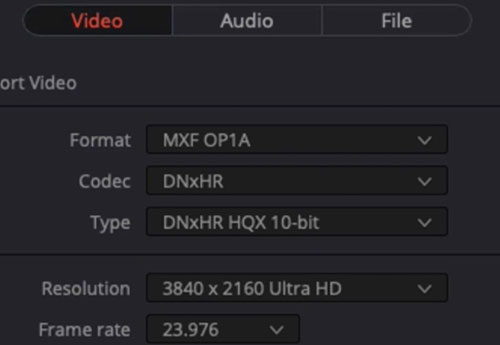 T he Avid DNxHR and Apple Prores codec families are designed to meet the needs of modern, streamlined post-production workflows. These days we capture source material on a variety of cameras- action cams, smart phones, drones and high-resolution cameras, and codecs makes it easy to work with any formats. With the growing demand for 4K deliveries, we need fast and reliable codecs that ensure reel-time playback while maintaining superior image quality. Both the DNxHR and ProRes families offer a variety of codecs for different compressions, data rates and file sizes. Some with just enough image information needed for editing, others for high-quality color grading and finishing, and lossless ones for mastering and archiving. Below are the full list of codecs from both families. #customers { border-collapse: collapse; width: 100%; font-family: Nunito; } #customers td, #customers th { border: 1px solid #ddd; padding: 8px; font-family: Nunito; } #customers tr:nth-child(even){background-color: #f2f2f2;} #customers tr:hover {background-color: #ddd;} #customers th { padding-top: 12px; padding-bottom: 12px; text-align: left; background-color: #ad00ff; font-family: Nunito; color: white; } Codec Color sampling Usage DNxHR 444 4:4:4 Finishing DNxHR HQX 4:2:2 Finishing DNxHR HQ 4:2:2 Mezzanine* DNxHR SQ 4:2:2 SQ Editorial DNxHR LB 4:2:2 LQ Editorial ProRes 4444 XQ 4:4:4 Finishing ProRes 4444 4:4:4 Finishing ProRes 422 HQ 4:2:2 Mezzanine* ProRes 422 4:2:2 Mezzanine* ProRes 422 LT 4:2:2 SQ Editorial ProRes 422 Proxy 4:2:2 LQ Editorial * In this case, Mezzanine means a compressed file that can be used to produce additional compressed files, but it is not necessarily useful for finishing work. Codec facts: DNxHR 444, ProRes 4444 and ProRes 4444 QC are the only codecs with embedded alpha channels. DNxHR 444 and ProRes 4444 XQ are the only codecs that fully preserve the details needed in HDR- (high-dynamic-range) imagery. Both codec families are resolution independent, but bitrate will vary depending on if you output a proxy file or a higher resolution file. Both codec families can be wrapped inside MXF or MOV containers. For more detailed specifications: Full DNxHR codec list Full ProRes codec list Codec differences DNxHR and ProRes was optimized to be visually lossless through many generations of decoding and re-encoding. Some claim to have noticed performance differences, but studies have shown that the quality and speed differences are negligible. An important difference, however, is that some of the major editing and finishing systems available lacks support for ProRes encoding for Windows. This means Windows users can read a ProRes encoded file, but in some cases cannot export one. For this reason, many post-production facilites have abandoned ProRes and implemented a full DNxHR workflow. There are systems that Apple fully supports such as the Adobe programs, Nuke and Scratch, but DNxHR is accessible universally. Another important reason for the success of DNxHR is that Avid can read the files natively from its own MXF file structure. This eliminates the need to import clips and timeline rendering. Lowepost
 -
C DL stands for “Color Decision List”. It is a metadata format developed by the The American Society of Cinematographers (ASC), in order to exchange rudimentary colour correction information between postproduction tools. It is sometimes necessary to apply non-destructive look communication instead of colour correcting an image directly. The colour correction is expressed as metadata, and the image is transferred without any creative decisions. This greatly simplifies the versioning of looks, because simple metadata can be updated without the need of re-transferring image data. CDLs are very common in VFX workflows because the VFX artist needs both the ungraded shot and the intended look. The ungraded shot allows the artist to comp in truly linear light, and the intended look is needed to check if the individual plates still hold together after the grade is applied. Slope, Offset and Power CDL defines a parameterised function to individually modify the red, green, and blue channel of an image. In addition, CDL specifies a global saturation. The three tone curve parameters are Slope, Offset and Power. These parameters are simple mathematical operations, which allow the colourist to modify the incoming data. “Slope” is a multiplier to the incoming data “Offset” is a summation to the incoming data “Power” is a power function to the incoming data The formula is: out.rgb=(in.rgb*Slope.rgb+Offset.rgb)^Power.rgb in.rgb = input red, green, blue values out.rgb = output red, green, blue values Slope.rgb = Slope red, green, blue values Offset.rgb = Offset red, green, blue values Power.rgb = Power red, green, blue values A fourth parameter “Saturation” is achieved by converting the out.rgb data in a Luma and Chroma component. The Chroma Signal is then multiplied by the “Saturation” parameter. Film Grade and Video Grade With Slope and Offset you can produce both a Film Grade “Exposure” and “Contrast” and a Video Grade “Lift” and “Gain”. Exposure is achieved by Offset Contrast is achieved by a combination of Offset and Slope Gain is achieved by Slope Lift is achieved by a combination of Offset and Slope Gamma is achieved by Power Formats A CDL Grade is specified by ten values, and they can be stored in different formats. Slope.red Slope.green Slope.blue Offset.red Offset.green Offset.blue Power.red Power.green Power.blue Saturation .cdl .cdl is a text file (with the suffix “cdl”). It has an xml like structure. It defines one CDL grade and looks something like: <ColorDecisionList> <ColorDecision> <ColorCorrection> <SOPNode> <Slope>0.904771 0.931037 1.011883</Slope> <Offset>0.008296 0.017804 -0.026100</Offset> <Power>1.052651 1.005324 0.945201</Power> </SOPNode> <SatNode> <Saturation>0.801050</Saturation> </SatNode> </ColorCorrection> </ColorDecision> </ColorDecisionList> .ccc .ccc is the same concept but can contain multiple CDL structures. .ale CDL values can be stored per shot in an Avid Log Exchange. .edl CDL values per shot can be stored in a CMX 3600 Edit Decision List. Colour Management Unfortunately, CDL does not define the image state and colour management pipeline in which this formula is applied. That means, these ten values describe a colour correction but do not describe the way you apply the values. The values applied in a Log Colour Space with a viewing transform on output will elicit a different result, then the same values applied in Display Space after the viewing transform. This is the reason why sometimes CDL values do not match between applications. In order to make CDL work, you need an additional Colour Management Layer that transforms the image into the correct state, apply the CDL values and eventually convert the image into another image state. In the field, there are different colour management frameworks like “OpenColor IO” or “Truelight Colour Spaces”. Some productions also just create “Lookup Tables” for the input- and output transformation and apply the CDL values by hand. Conforming The only way to automatically apply CDL values to multiple shots is using ALE and EDL. This makes CDL only applicable in very narrow workflows. .cdl or .ccc files do not store camera metadata, which makes it impossible to “bulk paste” CDL values to multiple shots. Often manual copy and paste takes place, which is a dissatisfying and time-consuming task. Some tools offer a smarter copy and paste functionality if the .cdl values are named like the filename or clip names of the shot, so the conforming metadata is stored in the filename. Big VFX Houses use their Asset Management System to deploy the CDL values to the correct shots. Conclusion CDL is a simple concept to describe and communicate a simple colour correction transformation in a software agnostic way. It does not specify or communicate the needed colour management information, nor does it store any shot based metadata. In order to make CDL work, a production needs an additional colour management and asset management pipeline to successfully distribute CDL values between software packages. Daniele Siragusano Colour and Worklow Engineer, Filmlight
-
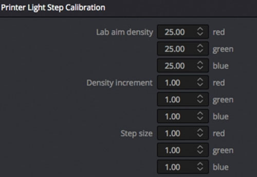 C olor timing is the process of balancing the color and density of each shot in a motion picture. This was necessary because motion pictures were filmed out of order from the final edited sequence, over a long period of time under varying conditions (lighting, exposure and film emulsions). Then the film negative was sent to the lab for film processing which also had variables which affected the color and density such as developing time, temperature and chemical balance. When the film negatives were spliced together into the final sequence to make a film print on positive film stock, it needed to be analyzed for color and density to set the printer lights for each shot so the final print would be balanced. Although the technical process of color balancing was done by the color timer, the process of reaching the final color was a collaborative effort involving the timer and filmmakers; usually the cinematographer, director, editor or other production assistants. This was done through screening film prints with the filmmakers, getting their comments and opinions then applying corrections to the film timing till final approval was achieved. This would take from 2 or 3 timing passes up to 10 or more depending on the nature of the film and demands of the filmmakers. The eyes of the color timer The tools needed to color time a film print begin with the eyes of the color timer. Before the first print is made, the film negative is viewed on a film analyzer such as a Hazeltine. This is a machine that reads the negative and presents a positive image on a video monitor. The color and density can be adjusted using knobs which represent the printer lights usually from a 1 to 50-point scale for each color (Red, Green, and Blue). The timer turns the knobs until the color and density look right so the printer lights are set for that shot. This is done for each shot of the film, then a print is made. The film print is screened by the color timer who will analyze with his eyes and make notes to what needs to be corrected. The film print is then put on a comparator projector where it can be viewed scene by scene to make color adjustments by changing the printer lights for the next corrected print. Read: Dan Muscarella about printer lights Some timers use color filters to help make color decisions. The color corrections are not seen until another print is made. Originally, these color corrections were written on a timing card which showed the footage and printing lights for each scene. The timing card was sent to a person who would have to make a paper tape with this information to be loaded into the printing machine. Now this information is input to the computer by the timer as he makes corrections and directly accessed by the printing machine. The length of time to color correct a cut negative film from the first trial to final approval can vary from a couple weeks to several months. This varies based on the number of scenes, how well it was shot, the need for reshoots or effect shots and the filmmakers demands. A typical turnaround from a first trial print to a corrected print including color correcting and printing takes several days. An average film would take 3 to 5 passes for approval which would be about 15 to 20 days total. Categories of color timers First would be the Daily Timer who would get the negatives from each day's shoot (dailies) and using a film analyzer, set printer lights for the daily prints. An Analyzer or Hazeltine Timer sets the printing lights for the edited (cut) negative to make the first print to be screened. The Screen Timer views the first print in a theater on a big screen taking notes for corrections to be made on the comparator. The Comparator Timer (usually same person as Screen Timer) views the print on a small projector and applies the corrections based on the Screen Timer's notes. With all the tools and complexities of today's digital color correction, it is easy to become too focused on micromanaging minor details and losing sight of the big picture. Film color timing was limited to color and density balance with emphasis on the overall scene to scene continuity. I would advise digital colorists to hold off using your specialty tools (secondary correction, windows, and mattes) until the overall continuity of color and density is addressed so the integrity of the cinematography does not get distorted. Now that I have been effectively retired from color timing with the closure of film labs and the industry taken over by digital projection I can only hope that the "art" of cinematography will go on. Working with some of the great cinematographers throughout my career taught me the importance of the image caught using the lighting, lenses, and techniques used by the camera. With the new technologies, it is important that this art does not get distorted by the involvement of too many opinions and people in the digital timing bay. My biggest advice is to listen to the cinematographer. Jim Passon
 -
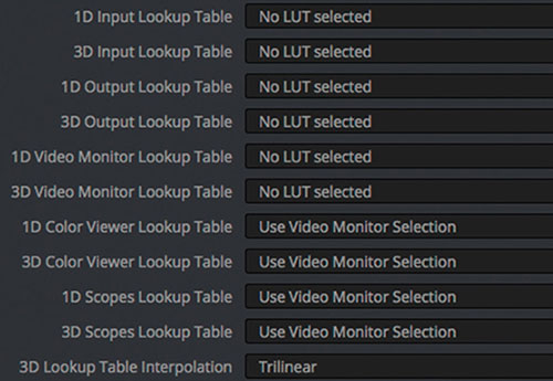 S imply put, a LUT is a Look Up Table. A LUT is used to transform a value (or a set of multiple values as in RGB) into another value or set. 1D-LUT Let’s first consider a 1D-LUT. A 1D-LUT is an array of values. For a 10-bit data system (such as the classic 10-bit Cineon Log data system), the values range from 0 to 1023, therefore, a one-dimensional array of 1024 elements can perfectly map each of the possible values into another. If the data is a 16-bit system, the array size needs to be 65536 long to accommodate all the possible input values. If for either case, the size of the array is a problem with the hardware/software, a subsampled array can be used (i.e., instead of 65536 elements for a 16-bit system, 256 can be used and the missing input values are then linearly (or another interpolation method) interpolated. On modern software systems that utilize floating point systems, i.e. OpenEXR, the data to be put through a LUT is converted to properly match the input domain of the LUT system. In modern color correction, the image is usually a three channel RGB system or some other three metric color system. One 1D-LUT can be applied to each of the three channels such as in the case of a 1D-LUT used to convert from log data to linear data. Alternatively, a separate 1D-LUT can be applied to each channel, for example, if the gain or color shift of each channel needs to change. In each case described, the channels are treated as independent, any changes in one channel does not alter any other channel. 1D-LUTs are normally used where the desired transform can adequately be described by channel independent processing (scale or RGB metric conversions, overall color changes like the ASC CDL [except for the saturation parameter]). 3D-LUT In most of the color data transformations, the three channels are dependent. Changes in one channel will alter the others. However, to use the same type of data set as a 1D-LUT, a 3-dimensional array that points to a three element set would be required. For a 10-bit system with 1024 elements, that would be an array with 1024^3 elements (1,073,741,824) each pointing to three numbers! And for a 16-bit system that would be 65536^3 (281,474,976,710,656). Clearly, these array sizes are too large to manage in today’s computers. In order to manage the system, the domain 1024, 65536 etc. is broken down into discrete intervals. There are many currently used 3D-LUT interval types used today. Some usual ones are 16^3, 17^3, 32^3, 33^3, 64^3 and 65^3. Others are possible. For a 17^3 3D-LUT in 10-bit space, each set of nodes of the three channels range from 0 to 1023 with an increment of 64. For the 65^3 3D-LUT the number of input nodes (each input point is called a node) is 65^3 (274625) which is far less than the 3D array system (281,474,976,710,656). 3D-LUTs are stored in the computer with an implied input. If one looks at a text based 3D-LUT, the numbers are the output sets and the input values are implied by the order of the list. Normally, there are two types of implied orders, the R fastest (or commonly referred to as inside) and the B fastest (most common). In order to use these 3D-LUTs, a 3D interpolation method is employed. Common ones are trilinear and tetrahedral interpolation which uses the input nodes and then linearly (occasionally other types such as cubic interpolation etc.) interpolated to obtain the output color R’G’B’ from the input RGB. Less commonly used 3D-LUT types do not have ordered nodes and are lists of input RGB to output R’G’B’ and are called cloud based systems which have their own types of interpolation methods. For these systems, the interpolation times are usually longer due to the increased processing involved. Types of 3D-LUTs Digital camera input LUT Used as a color corrector input LUT to transform the camera R G B into some desired standard or creative look. Calibration LUT One type is the film emulation LUT. These types of LUTs are derived from film negative and film print densitometry of discrete patches originating from a film recorder and a film print. These LUTs “calibrate” the display in the color correction room such that the image on the screen is a close match to a print viewed on a film projector. Post houses without their own film projectors can assure proper film out results with a quality 3D-LUT. It is possible to achieve the same look without using a LUT as long as the color correction hardware and software has the capability to process the images from the starting position to the desired position. And, of course, as long as the desired position’s look is known to the colorist. In the case of the film emulation LUT, it is probably very error prone and/or time consuming to have a colorist try to match a print on a film projector to the digital display for each scene in a consistent manner. Creative LUT Many times a creative look is desired and a specially created 3D-LUT can assure that the look is applied consistently on varied scenes. The colorist can then concentrate on minor changes from this base look provided by the LUT. Some examples are LUTs derived from older cinema systems such as Technicolor two-strip or bleach bypass etc. The output of these LUTs can then be altered by the colorist for the desired effect. I have created LUTs that desaturate all colors except reds and maintain the hue and saturation of flesh. This is a very specific LUT to create a starting point for the colorist. In some cases, the look desired by the production team stretches the ability of the controls on the color correction platform. A properly created 3D-LUT can provide the look while the color correction platform has its controls in the center positions, allowing for further creative control. Technical LUT Sometimes a 3D-LUT is used to transform a project from one type of display to another. Some examples are: P3 to Rec-709 2D P3 to 3D P3 D6500K P3 to D5500 P3 Rec-709 to P3 Transform standard display (i.e., P3) to a non-standard type such as Plasma, OLED or Laser display Technical LUTs may be provided by the camera manufacturer for certain purposes. For example, a LUT may be provided to transform the camera data to ACES data for ingest into the color corrector. Post house engineering staff, color scientist, can create specific technical LUTs for a variety of purposes. P3 to Cineon DPX LUT Some post houses use as their workflow a digital cinema P3 data-centric system. This is due to the deliverable to the production is mostly for digital cinema venues and they do not want to limit the image to a film print. Other display types that are common, such as Rec-709 can be created from the P3 data (with some mild gamut remapping of the larger color P3 system into Rec-709). In these cases, it is desired to use a 3D-LUT to transform the P3 data into Cineon 10-bit DPX data for film out if a small number of film prints are requested by the production. The generation of an accurate 3D-LUT for this purpose is very complex. The P3 data can be out of the film print’s color gamut and needs to be gently remapped. I have developed a sophisticated computer model to create these types of LUTs. The film out results is exceptional. Viewing LUT (Show LUT) The Viewing LUT is what the colorist uses in the normal viewing of the digital data in the suite. It depends on what the data metric of the source is. If it is a digital camera, then the LUT will convert it to P3 directly, or if the camera LUT is a camera to Cineon DPX LUT then that LUT can be combined with the Calibration LUT (which converts Cineon DPX to P3) to get the Viewing LUT. So, the Viewing LUT is whatever LUT that can take the source data metric and convert it to the metric used for the digital projector (usually normal P3 but can be Rec-709, P3 @ 6000K white point or P3 @ 6500K white point etc.). Float conversion LUT The Float conversion LUT can be useful, however very few LUT interpolation algorithms can effectively work with the implied data range of EXR. For example, a normal Cineon DPX 0-1023 log data set is roughly to -0.05 to 13.5 in linear EXR. But, the "usable" EXR range for display is 0 - 1.0. Which means that the LUT must convert the EXR range into a viewable range. Commonly, since the LUTs can only handle an implied range of 0 - 1.0, the data is manipulated by the colorist to take the wider EXR range and artistically compress it into the domain the LUT can handle. One problem with the EXR metric is that it is normally linear. Linear data going through a LUT is not efficient. For an EXR linear range of -0.05 to 13.5, that is a 14.0 range and if the displayable range is 0 - 1.0 that is only ~7% (1.0/14.0 = 0.0714). That means that for the size of the LUT in nodes (33^3, 65^3 etc.) only 7% is used and interpolation artifacts can show up. For a 33^3 LUT, there are 33^3 = 35937 nodes and 7% is only 2567 nodes used, the rest are not used. Schemes such as introducing a gamma or log on the data can effectively compress it for LUT conversion, but it takes some color expertise to create the LUT. On most modern color correction platforms when they use the LUT conversion, the system re-scales the data to 0 - 1.0 LUT input to interpolate through the LUT. Mathematically other domains are possible, but typically all positive values are used. Inverting a LUT Whether the LUT used is a 1D-LUT or a 3D-LUT, the process of going backwards is possible but plagued with some problems. If the transform going forward through the LUT gives the same output for multiple inputs, then it is not possible to “guess” which of the inputs produced the output. Further, the output domain of the LUT may be different from the input domain. For example, it is common to want the RGB triad that gives a specific XYZ on a display. Going forward from RGB to XYZ is relatively simple since we can pass a set of patches on a display and measure the XYZ values and create a 3D-LUT. However, the domain of the XYZ is limited by the gamut of the RGB primaries and white point of the display. The inverse 3D-LUT needs to accommodate the full XYZ range possible and complex gamut mapping techniques need to be applied to be able to produce an operationally correct 3D-LUT. Even with these techniques, proper statistically sound results are achieved that may not be entirely accurate. There are certain LUTs that cannot be inverted. For example, a LUT that creates Black and White (or some tone like sepia) from a color image. A color image cannot be derived from a single black and white image. The creation of LUTs Many techniques are used to create LUTs. 1D-LUTs and 3D-LUTs may be created by applying a mathematical transform to a unity LUT. In the case of a 1D-LUT, a unity LUT is an array where the values are the indices (for example, a unity 1D-LUT give 233 output for a 233 input etc.). A unity 3D-LUT has the output R G B set equal to the input RGB. Some examples of LUTs that are created mathematically are Rec-709 to linear, linear to sRGB and gamma (2.6 gamma for digital cinema) to linear XYZ. LUTs that are created from non-equation systems are from measured data derived from actual color patches (either on film or on measurements from values sent to a display device) or very complex system computer models. For the systems from measured data derived from actual color patches, usually only a small portion of the total color space of the LUT is measured and the nodes not measured are interpolated via conventional techniques. Systems like Truelight (from Filmlight) utilize a bit over 1200 film patches (via an auto-reading densitometer) and where the measurements are done from displays many more patches can be measured depending on the characteristics of the measuring device. A larger number of patches usually reduces error in the created 3D-LUT. Certain 3D-LUTs, i.e. P3 to Cineon DPX LUT, benefit from large patch sets. Typically, I use 9000-10000 film patches to create these 3D-LUTs. If less than the actual number of nodes in the 3D-LUT is measured, some error is introduced by the interpolation method. Mitch Bogdanowicz
 -
A change that solves the issue has been implemented Monday night and the website should now be available for most of our clients. Please do not be alarmed if it doesn’t work yet for you – The solution is implemented but it might take a bit of time for it to take effect. We will of course continue to supply assistance wherever required.
-
Thanks for the feedback Brandon, completely my mistake. It's fixed now 🙂
-
We continue our DaVinci Resolve 17 training with a brand new high-end course in Color Management Workflow. This is an intermediate course for colorists and visual effects artists taught by our master instructor Lee Lanier. In this training series you will learn to work with both display-referred and scene-referred management including ACES, applying DRTs with SDR and HDR projects, using DaVinci Wide Gamut, matching camera profiles with color space transforms, DCTLs and Cinematch, how to set up your projects for multiple color space outputs, RED IPP2 and RAW workflow, how to use the Gamut tool, LUTs, CSTs and OpenColorIO in Fusion, an overview of the Colorspace Aware Tools and much more. The DaVinci Resolve project files and footage are available for download so that you can easily follow along. Download project files The DCTL that comes with the project files is created with a tool called Resolve Math Extra (OFX) developed by Paul Dore. It can be downloaded from this site. About the instructor Lee Lanier has created visual effects on numerous features films for Walt Disney Studios and PDI/DreamWorks. Lee is a world-renowned expert in the video effects field, and has written several popular high-end software books, and taught at the Gnomon School of Visual Effects in Hollywood. Who is this course designed for? Colorists Visual effects artists Lessons overview L01: Introduction L02: Color terminology and workflow overview L03: Display referred vs scene referred L04: Display referred space and LUTs L05: Adding LUTs and DCTLs to resolve L06: Matching cameras with an OFX plug-in L07: Mixing camera footage in display referred L08: Color management in Fusion L09: Resolve color management L10: Working with ACES L11: RCM and ACES with Fusion L12: Adding color transformations in Fusion L13: Using opencolorIO L14: Matching cameras with Cinematch L15: Switching the RCM wide gammut L16: Setting up HDR in RCM and ACES L17: Using color scopes with SDR and HDR L18: Working with colorspace aware tools and HDR grade Software required A free version of DaVinci Resolve or DaVinci Resolve studio
-
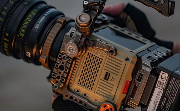 When the Red Komodo 6K camera hit the market with its exceptional image quality, global shutter and small versatile form factor for an affordable price, it took the industry by storm. The modular design of the camera empowers the users to customize it for any production environment, and we’ll take a look at some of the accessories available. Camera cage A camera cage provides protective armor and several mounting points for mounting accessories. It allows you to connect different battery solutions, monitors, microphones, handle options, and attach the camera to tripods and gimbals. This cage is is probably the most popular one, from Tilta. Other popular cage providers for Red Komodo are Smallrig, Shape, 8Sinn, Nitze, Kondor Blue and the more expensive Wooden Camera and Bright Tangerine. Monitor The small screen on the top of the Red Komodo camera body is not a perfect option for shooting, so adding a traditional 5” to 7” monitor is a better option. That will also let you control many settings via the touchscreen like white balance, shutter angle and even more advanced features like aperture changes of electronic lenses and autofocus point selection. Popular camera monitors to check out are Atomos Ninja V 5”, SmallHD Pro Focus 5” and the Portkeys 5” BM series. In the 7-inch monitor range, have a look at Atomos Shinobi. For an even larger screen, the 9” BM090 from Flanders Scientific is worth checking out. It’s a camera version of FSI’s high-quality broadcast and color grading monitors, full of useful features. Handles The most popular side handle for Red Komodo is their own low profile Red Outrigger handle with integrated Record Start/Stop button. Red also offer their Wing Grip top handle, but there are many third part alternatives to choose from, from the same companies that create cages for the camera. Some top handles like this one from Smallrig have mounting holes for a tilt monitor mount in front which can be important for center aligning the monitor for better balance. There are also handles like this one from Smallrig that can slide in both directions or swap 180 degrees for situations that require a different grip. A popular, but more expensive one is this from Wooden Camera. Battery System The Red Komodo body can take two small Canon batteries (BP-955 or BP-975), their own Redvolt BP or cheaper Red Approved alternatives from Blue Shape or Jupio. There are also some Red Compatible (not Red Approved) alternatives that provide enough current to power the camera and have been tested and deemed safe for use. Just remember that these batteries do not communicate with the camera and therefore are unable to display battery percentage and remaining time. For more power, consider adding a V-mount plate and larger V-mount batteries. Audio Most cinema cameras are not designed for high-quality audio recording and requires an external audio adapter. The internal audio comes with excessive amounts of hiss when it’s gained up, and the adapter is needed to get a clean audio signal. When using the adapter, the camera preamps can stay on low gain for best performance while the adapter does all the heavy lifting. That way we can push the gain and get high-quality audio. The most popular one is RED-DXA from Beachtek. It’s phantom-powered dual XLR adapter with low-noise preamplifiers. It gives you everything you need to record cinema quality audio. It can be mounted on the rods with rail blocks, or installed on the side of the cage with the click-release plate that comes with the adapter. It’s designed for RED and the industrial design look makes it integrate nicely with the look of the camera body. While talking audio, our favorite microphone is the MKH 8060 from Sennheiser. It’s the successor of the legendary MKH 416 and a state-of-the-art shotgun microphone. Technically speaking, the MKH 8060 main difference is that its off-axis sounds is not affected by any coloring and it has a lower end, which is often asked for by filmmakers. It’s also a bit shorter and therefore ideal for a small camera like the Komodo. To mount the microphone, this microphone holder can be mounted directly on every cage. Lens Equipment, follow focus and matte box A Red System often consists of a base plate and 15mm rods that can be attached to the camera cage. The rods can be used with a lens support or to attach a Follow focus system. We recommend the Mini Follow Focus from Tilta as that’s super small, rock solid and the most affordable option on the market. If you choose to use non-cine lenses on the Komodo, follow focus gear rings are needed. Non-cine lenses do not have built-in 0.8 module gearing for use with follow focus systems, so that has to be purchased separately. Luckily, Outlast Cinema Gears can be ordered super cheap from Couto Camera for both the focus and aperture barrels. They have gear rings for every lens available at any size and ships quickly worldwide. It’s important to know that ultra-rigid gears in aluminium makes noise during pulls, but the ones from Couto are near-silent which is important when having a shotgun microphone mounted on the camera. For a small camera using non-cinema lenses, a lightweight mattebox is preferred. Tilta is offering the smallest solution on the market which is designed to be mounted directly onto the lens. Media Management The Komodo takes standard CFast 2.0 cards, and several producers offer RED Approved Media. Angelbird and Exascend are trusted by the industry and offer the highest sustained performance (read and write speed) throughout the capasity of their cards. That means you can record without dropped frames in all cinematic modes. Angelbird and Exascend are also the only ones who offer approved media up to a capacity of 1TB, and they cards are built with magnetic, x-ray, electric discharge, overload and temperature protection. To take advantage of the incredible dynamic range in the camera and achieve superior image quality with the right post-production process, watch this training series from Lowepost. The RED Post Production training is designed for beginners and no post-production experience is necessary. Additional accessories There are tons of additional accessories available for Red Komodo including RF to PL mounts, I/O modules, filter mounts, cables, and small cable management devices. New accessories hits the market every month and you will find what you need to build your ultimate camera. Happy building! This post might include affiliate agreements, for full information click here.
 -
Tracking Complex Surfaces in Nuke 13 & Mocha
Sjors Krebbeks commented on Sjors Krebbeks's course in Finishing & VFX
Thanks for letting us know, it's fixed now 🙂 -
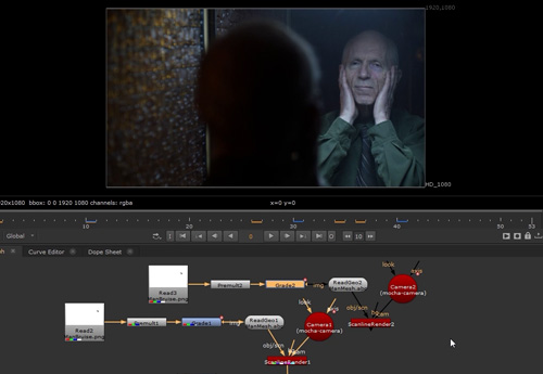 This course is about motion tracking complex surfaces in Nuke 13 and Mocha Pro, and taught by master trainer Lee Lanier. You will learn how to add digital make-up, tattoos or scars to organic surfaces such as rippling skin, reflections to curved surfaces, and elements to complex surfaces such as flapping flags or undulating clothes. Nuke and Mocha Pro is the perfect combination for all compositing tasks and Lee will teach you the techniques you need to be confident to solve the most complex shots. The course is easy to follow and designed for both beginners and professionals. The footage and project files used in this course are available for download. Download project files About the instructor Lee Lanier has created visual effects on numerous features films for Walt Disney Studios and PDI/DreamWorks. Lee is a world-renowned expert in the video effects field, and has written several popular high-end software books, and taught at the Gnomon School of Visual Effects in Hollywood. Who is this course designed for? Compositors Finishing Artists NUKE Users After Effects Users Mocha Pro Users
 -
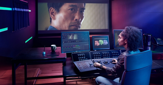 This is the ultimate course for editors and conform artists who want to learn everything about conforming inside of DaVinci Resolve! With 21 lessons and almost 5 hours of in-depth DaVinci Resolve training, Kevin McAuliffe will take you through every step and technical detail of the process from conforming media to mastering the final picture. About the instructor Kevin is an award winning editor and visual effects creator based in Toronto with over 15 years of teaching and training experience. Over the past years Kevin has delivered world-class work for clients such as Warner Bros, Walt Disney Company, 20th Century Fox, Universal and Elevation Pictures. Who is this course designed for? Editors Conform Artists Colorists Software required A free version of DaVinci Resolve or DaVinci Resolve Studio. Avid. Premiere and Final Cut X are used in some of the lessons. This training series is sponsored by our friends at digitalrebellion.com
 -
Hud Hexagon in Cinema 4D & After Effects
Sjors Krebbeks commented on Lowepost's course in Hud Element Design
Glad to hear that you enjoy the course and thanks for the report! Must have been a typo in my end. I have fixed it 🙂 -
Sorry about that, Lesson 2 is available now.
-
Sometimes a dream might become reality before you know it 😄
-
T he Scratch Essential Training is designed for new Scratch users, and DaVinci Resolve colorists who are looking to add another excellent conform and finishing tool to their toolkit. Kevin P McAuliffe covers all the basics you need to know to perform the most common tasks that you do on a daily basis so that jumping in or making the switch will be as smooth as possible. About the instructor Kevin is an award winning editor and visual effects creator based in Toronto with over 15 years of teaching and training experience. Over the past years Kevin has delivered world-class work for clients such as Warner Bros, Walt Disney Company, 20th Century Fox, Universal and Elevation Pictures. Who is this course designed for? Editors Conform Artists Colorists VFX artists Lessons overview (subject to change) Lesson 01: Getting Started Lesson 02: Working in the Construct Window Lesson 03: Working in the Edit Module Lesson 04: Working with Layers in the ColorFX Module Lesson 05: Working with Versions in the ColorFX Module Lesson 06: Working with Qualifiers in the ColorFX Module Lesson 07: Working with LUT's and Comparing Grades Lesson 08: Effects, Transfer Modes & Mattes Lesson 09: Nodes Lesson 10: Creating Dailies Lesson 11: TBA Lesson 12: TBA Lesson 13: TBA Lesson 14: TBA Lesson 14: TBA Software required Scratch (20% discount for Lowepost premium members)
-
Great job!
-
Base Grade and the evolution of grading tools
Sjors Krebbeks posted an insider Article in Color Grading
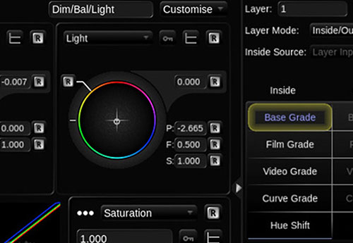 The color-grading specialist Filmlight caused a bit of stir in the colorist community at NAB 2016. They introduced Base Grade, a new grading operator for Baselight. Base Grade is intended to replace classic tools such as 'Lift', 'Gamma' and 'Gain'. That sounds like a small revolution. Filmlight promises more consistent results compared to existing tools and a more natural working style. This is reason enough to take an in-depth look at it - not only for Baselight colorists. For the evaluation of Base Grade, a rough understanding of the evolution of color correction helps. The origins of color grading, as we know it today, date back to the beginnings of television and cinema. For television, video signals originating from TV cameras or film scanners always had to be adjusted or corrected. The profession of the colorist emerged in the telecine, where film footage was transferred into a pleasing video signal. VideoGrade The technicians provided the colorist with four basic technical parameters to shape the video signal: 'Lift', 'Gamma', 'Gain' and 'Saturation'.These are still among the most popular grading tools. In Baselight, one can find them in the VideoGrade operator. The colorist adjusts the black level of the video signal with 'Lift' (sometimes referred to as 'Pedestal') and the white level with gain. For those who are experienced in Photoshop, it makes sense to visualize the resulting gradation curve: 'Lift' sets the starting point (bottom-left) and 'Gain' the end point (top-right). When working with VideoGrade, these are the most important points of reference for the colorist. 'Gamma' is technically a power function whose only parameter is the exponent. The gamma function determines the curvature of the gradation curve between the two endpoints. These three parameters can be adjusted not only for the brightness, but for all three color channels of the video signal (RGB). However, individual controllers for red, green and blue are usually not presented to the user. The user has one controller for the brightness signal and a two dimensional controller for the color component. This results in the basic layout of all grading control surfaces: Three trackballs that adjust the color two-dimensionally and around them a rotating ring for the luma adjustment. 'Lift' is on the left, 'Gain' on the right and 'Gamma' in the middle. These three parameters are often colloquially referred to as shadows, midtones and highlights. With the help of an RGB waveform monitor, these adjustment possibilities have proven to be very efficient to forge a video signal within the given technical specs. A very popular and proven working method of video-style colorists is to first adjust the black and white point of an image. All three channels are balanced both in the blacks and in the whites just before clipping. The brightest point in the image is then pure white, thus without color cast and with maximum brightness. The darkest point is pure black. People often speak of "clean" blacks and whites in this case. Next, the 'Gamma' parameter is set. It adjusts a combination of brightness and contrast. If one wants to put a color tone on the picture, this is often done with the 'Gamma', since then black and white remain “clean”. Baselight provides two modes for VideoGrade. The default mode is RGB. In the Y'CbCr mode, the luma channel is processed separately. Brightness or contrast changes will then not affect the color and saturation of the image. Over time, VideoGrade has proven to be the most important tool of telecine-style colorists. They convert high dynamic range images (e.g. log encoded) manually to the desired output color space utilizing the available grading toolset instead of a technical color space conversion (e.g. a LUT). This means that nowadays VideoGrade is not only used, as originally intended, on images in a video color space, but also for images in log color spaces. The 'Lift', 'Gamma' and 'Gain' trio is probably the most commonly used grading operator in the current video world. However, it dates from a time when handling features such as specular highlights was not that important. Burned out windows or skies were tolerated as long as the faces looked nice. A soft-clip, a gentle transition into the over-exposure, is not realizable with VideoGrade alone. Over time, video colorists developed different techniques to meet this aesthetic demand. Gradation curves, luma keys, blend modes and specialized soft-clip operators are among the techniques that have been used for this purpose. A further disadvantage becomes obvious in VFX workflows. Contemporary compositing works the most realistically in a scene-referred linear color space. Then pixel values are proportional to light photons on the set. VFX pre-grading might still make sense to adjust the general brightness and white-balance and to match shots in a sequence. Unfortunately, 'Lift' as well as 'Gamma' and 'Gain' destroy the scene-linearity of a shot and make VideoGrade impractical for this type of VFX pre-grading workflow. FilmGrade Long before the telecine colorist, the profession of the film color-timer emerged. They determined the look of a film by adjusting the intensity of printer lights and chemical processes in the film lab. This profession required a lot of experience and intuition. Contrary to the telecine with its sometimes saturated or harshly clipped colors, the analogue lab process has film-stock as an aesthetic foundation. With the introduction of the Digital Intermediate process (DI) around the year 2000, the new profession of the DI-colorist arose. DI-colorists correct images digitally before they are recorded onto intermediate-film and printed. The footage usually originated from film as well and was scanned to Cineon log color space. The DI gradually replaced the analogue intermediate process and thus the creative part of the color-timing in the lab. Film is a key component of the DI process, since one is restricted to the colors that can be reproduced in the film print. The lab processes generating the film print and the projection are therefore simulated live during the grading with a film print emulation look-up table. The so-called 'Film LUT' is applied in the preview output and causes the images to react differently to input from the colorist compared to telecine or video mode. The manufacturers developed new grading tools for the DI process based on lab color-timing. In Baselight, the tool is called 'FilmGrade'. Some film-style colorists have previously worked as color-timers and thus got an easy entry into digital color correction. FilmGrade is designed for images in Cineon-Log color space. After the color correction, the image is converted into a display color space (e.g. DCI P3) utilizing a LUT or the more recently available GPU-shaders of Truelight Colour Spaces dating from Baselight 4.4. FilmGrade consists of six tools divided onto two tabs. The main page consists of 'Exposure', 'Contrast' and 'Saturation'. The second page consists of 'Shadows', 'Midtones' and 'Highlights'. All tools offer a trackball and a rotatable ring. The most important tool is 'Exposure', which can be adjusted in RGB printer light steps via the Blackboard control surface. 'Exposure', which is also referred to as 'Offset' in other grading software, controls the general brightness and color of the image. Film style purists try to work as much as possible with 'Exposure', because then the image remains very natural. The contrast in all color channels and the scene-linearity are basically retained during 'Exposure' changes. Color Timing - The 'Exposure' tool in FilmGrade not only simulates the work with printer lights, but also translates the correction to printer points. 'Contrast' and 'Saturation' seem self-explanatory. However, the trackball color-setting controls deserve an in-depth look. With the 'Saturation' trackball, the colorist controls the saturation of opposing colors in the color circle. For example, when you move the trackball towards the warm tones (yellow, red), these become more saturated. At the same time, the cold tones (blue, cyan) are desaturated. The 'Contrast' trackball, on the other hand, is used to tint the highlights and shadows in complementary colors. The corresponding pivot point is important when working with 'Contrast'. It defines the center of the curve and thus the strength of the effect on the highlights and shadows. 'Shadows', 'Midtones' and 'Highlights' in FilmGrade are not identical to 'Lift', 'Gamma' and 'Gain' because the luma working ranges are limited via pivot points. When you raise the 'Shadows' level, for example, the curve is warped only until a defined point. With 'Lift', on the other hand, the entire image is changed, but the shadows are affected the most. It is difficult to determine maximum black and white with film because the transfer curves are very flat and non-linear in these regions. That is why the LAD grey patch, roughly in the middle of the curve, is the anchor point for both the calibration and the colorist. (The laboratory aim density patch was invented by Kodak and is a bit darker than 18% middle grey. You can find it on the Kodak website. A film style colorist does not care much about whether he hits 100% black or white. A soft clip is automatically active in this system because of the film print emulation. Scopes are less important and the visual impression is mostly guiding decisions. Thus, FilmGrade is a more natural grading concept than VideoGrade. Today, FilmGrade is used not only on Cineon log data, but on any kind of log encoding such as LogC from Arri. More modern approaches like ACES are also used in the output path in addition to film print emulations. There are fundamental problems with this concept as well. The 'Exposure' tool adjusts brightness quite naturally, but it is not exactly like changing the lens aperture or the ISO value. The reason for this lies in the underlying log encodings which, for example, do not define the black value to zero. The detailed explanation is beyond the scope of this article. Another problem is the future proofness. Log encodings can store only a limited amount of dynamic range. The Cineon curve, for example, was not sufficient for the high dynamic range of the Alexa camera. Therefore, Arri developed the LogC curve. Future cameras and HDR displays will require additional tweaks that might be compromising. This also applies to the VideoGrade Operator, which was designed with standard dynamic range video signals in mind. Base Grade: Under the Hood The time has come for a next generation color grading operator. Filmlight uses neither a video signal nor film stock as a foundation, but algorithms modeled on human perception. The dynamic range of Base Grade is not limited by a technical format like Rec.709 or the Cineon coding. It is ready for the HDR future. Base Grade works the same way in every working color space. Therefore, it always feels the same for the colorist regardless of the camera used. This requires not only precise color setup in the scene settings but also correct tagging of the footage. Usually this happens automatically, but for transcoded footage it might require manual adjustments. Base Grade converts the image autonomously into a linear color space in which, as in the case of linear compositing, the original brightness ratios of the scene are restored. The user does not have to care about the internal color space conversions because Base Grade hands the image over to the next operator in the defined working color space. Internally, Base Grade uses an Lab-based color model consisting of a pure luminance component L and two color components a and b. The color plane spanned by a and b was distorted by the developers in regards to color grading. This gives color and saturation changes the same visual effect in all color regions and makes the work feel more intuitive. All exposure values and pivot points are specified in aperture stops. This is a well known unit that mimics human perception and is easy for photographers and DPs to understand. The colorist can give instantly meaningful feedback to the DP. For example: "I made the whole picture half a stop brighter”, or “I lowered the Highlights one stop". If a Dailies colorist uses Base Grade, such feedback — comparable to the camera report from the lab in the past — could conceivably help the DP working on the set. It will definitely make communication between the DP and the colorist easier, especially when the DP is not physically present. Four parameters affect the whole image: 'Flare', 'Balance', 'Contrast' and 'Saturation'. Beside these global parameters, Base Grade partitions the image into brightness zones. This is reminiscent of the legendary zone system by Ansel Adams, which according to the developers served as a source of inspiration. The reference point of Base Grade is medium gray, as found on 18% grey cards. The luminance zones are defined from there in stops. A correction of three stops up or down is the maximum in the standard mode. This is generally sufficient. In extreme cases, up to six stops can be corrected in extended mode. At first glance, there are few parallels to existing tools in Baselight or comparable grading software like DaVinci Resolve. The RAW development experience in Adobe Lightroom comes closest to that in Base Grade. However, Base Grade offers not only luminance controls per zone, but also color and saturation. In addition, each zone's region can be fine tuned via 'Pivot' and 'Falloff', which makes it much more powerful. 'Balance': Adjusts the exposure and the color balance of the entire image. Brightness changes behave exactly like the change in aperture or ISO value. The trackball corresponds to the white balance. 'Balance' can therefore replace settings in a RAW decoder. The scene-linearity remains intact while working with 'Balance'. 'Flare': Influences the lower part of the curve by defining the zero point. A correctly set 'Flare' value is crucial for proper functioning of Base Grade. Otherwise, the real brightness ratios from the set can not be restored. The zero point is usually the darkest point of the image. 'Contrast': Adjusts the image's global contrast. In contrast to other implementations, crushing the shadows is prevented by the 'Flare' parameter. 'Contrast' works achromatically, which means it does not affect the saturation of the image. The colorist controls the intensity of the effect on the shadows and highlights using the 'Contrast' pivot- as with FilmGrade. 'Saturation': This is self-explanatory: the color intensity of the image. The crucial difference from conventional implementations is the visual uniformity, which works in a more natural way 'Pivot': The user adjustable starting point of the zone. It is defined in stops in reference to medium grey. For example “-1” means one stop below 18% grey. The 'Dark' and 'Dim' zones range from pivot to black, the 'Light' and 'Bright' zones from pivot to white. 'Falloff': Describes the transition until a zone has full effect. 'Falloff' is not measured in stops because it changes adaptively relative to the set 'Balance' to avoid negative slopes. Therefore, it is an abstract value ranging between 0 and 1. User interface The user interface follows VideoGrade and FilmGrade. It consists of three main parameters mapped to the three trackball-ring combos on the Blackboard control panel. Below lies a visualization of the current grade as a tone curve, framed by further parameters such as pivot points. The developers have distributed Base Grade onto two tabs. The first page is 'Dim' / 'Balance' / 'Light' and the second 'Dark' / 'Balance' / 'Bright'. The most important parameter, 'Balance', is permanently visible and mapped to the middle trackball-ring combo on the Blackboard. 'Flare', 'Contrast' and 'Saturation' are also visible on both pages and can be adjusted via encoders. Look and Feel - The Base Grade user interface. As usual, users can create custom layouts on new pages. The grade visualization display contains a special goodie. A luma waveform of the current image is superimposed over the curve. Thanks to this, the colorist constantly sees which parts of the image he is currently editing and how he should adjust the pivot points. It would be even more useful if the display superimposed a luma histogram. Test-drive It takes some time to get used to the new toolset. However, curiosity and the excitement of playing around with a new toy fuel one’s motivation to dig deeper. I tested the promise of the exact stop scale. Indeed, a 'Balance' boost of 1.0 shows the same result as doubling the ISO value in the RAW developer. And this applies for all tested cameras by Arri, Red and Sony. The clever part there is that you don't need RAW material for that. If you work with a mixed ProRes and ArriRAW Timeline, for example and all RAW shots have been pushed by one stop, you can now apply the exact same correction to all shots. And it is no longer necessary to switch to the DeBayer settings, because adjusting the exposure with Base Grade does not compromise image quality in that case. Unity – Below is pushed one stop in the RAW settings and top with Base Grade. The results are identical. White-Balance should be adjusted with the 'Balance' trackball. It will not yield the same results as the RAW developer because of the ab color plane that was specifically optimized for color grading. In my opinion, the results are a bit more pleasing than adjusting the Kelvin value in the RAW settings. Matching shot to shot seems to be another ideal task for the tool. Many colorists divide their grade into a basic correction per shot and the creative look. Used as the first layer in the stack, Base Grade makes it easier to compensate for exposure differences due to the scene-linear working style. Shots with diffuse lens flares are a common problem while matching. They cause raised black levels in the frame. Even quite clean lenses such as the Master Primes show this effect, especially when there are bright backgrounds. When you try to minimize the flare with VideoGrade’s 'Lift', for example, you mess up the whole picture and the grade does not fit properly anymore. The 'Flare' parameter helps in these cases because it corresponds to optical flare in the lens. If the exposure is basically correct, the differences in the black level caused by lens flare can be corrected quite well. With the help of the 'Flare' parameter, the colorist matches scenes that contain a lot of lens flare. When copying corrections from shot to shot, the colorist should also pay attention to the 'Flare' value and adjust it if necessary. For example, if you copy from a scene with lots of diffuse flare, the black will probably be crushed in the target shot. With none of Base Grades other controls except 'Flare', you can get it back to a decent level. If 'Flare' is set correctly, the black can practically never be fully crushed. Base Grade pushes the shadows into a pleasant-looking compression instead of a hard-clipping. The 'Saturation' control yields pleasant results too. It is astonishing that a tool as widespread as color saturation could be improved further. Base Grade gives more visually pleasing results than existing implementations in a direct comparison. With classic saturation tools, primary colors such as red quickly become overweighted in the frame as you increase saturation. With Base Grade, the strength of the effect is more evenly distributed over the color circle. And the great thing about this is that it works similarly while desaturating pictures. Evolution - next generation of color saturation. Top: A scene containing strong neon colors reduced by 30% with a classic saturation implementation. Bottom: Same reduction with Base Grade. Not only the colors, but also the brightness seems more natural. Base Grade reveals the full extent of its strengths with the zone model. The gradation of an image can now be modeled very precisely utilizing only one operator. With previous software, the colorist was forced into detailed and sometimes fiddly tweaking in CurveGrade or keying. Now there is a more intuitive alternative. For example, optimizing sky definition usually requires luma keying the highlights. With Base Grade, I got amazingly far without any secondary correction. On one shot for example, I initially lowered 'Light'. Next I lifted 'Bright' to tickle out the last details just before clipping. By initially adjusting the correction quite aggressively, I could easily find the right pivot points. Then I reduced to a more pleasing level. If the colorist opts for extremely strong corrections, there is a risk of unsightly effects, a preliminary stage of solarization. Base Grade prevents true solarization - negative slopes of the gradation curve - but the colorist can flatten the curve so much that the definition is ruined in certain brightness zones. In these cases, a larger 'Falloff', the transition of the zone, provides some relief. However, it also reduces the effect. Top: Uncorrected. A difficult shot, as the tonal values are compressed in the shadows as well as in the highlights. Bottom: Avoiding any keys or shapes, just modeling the gradation with Base Grade one obtains a picture with clearly more definition in the crucial areas. Base Grade also performs strongly with Cross-Process Toning, a common case in color correction. The highlights and the shadows are given different hues. Complementary hues are often chosen for this. The shadows, for example, are tinted in cold teal and the highlights in warm orange. Colorists often use HLS keys for this technique to have more control over the effect. With Base Grade and its zone model, one can precisely control the strength and hue of the effect and probably save some keys in the timeline. About VFX pregrading: Flare is an artifact that arises in camera lenses and distorts the scene-linearity. With the aid of Base Grade, the correct brightness ratios on the set can be reconstructed by setting the correct 'Flare' value. Something true black or the darkest shadows in the frame should usually be set to zero. After that, 'Balance' works completely scene-linear. Because of the flare correction, Base Grade is therefore better suited for scene-linear pregrading than 'Exposure' / 'Printer Lights' in FilmGrade. Conclusion Base Grade is very powerful, but it is also complex. Thoughtful setup of the project is essential for proper functioning. If the color space settings are a mess, it will not work properly. My advice is to slowly familiarize yourself with the tool and then integrate it into the daily working style, bit by bit. A good start would be, for example, to perform saturation corrections with Base Grade. The next step would be to make the basic correction from shot to shot, and so on. The new grading concept could also be a good starting point for Adobe Lightroom experienced photographers and DPs to color correct moving images because of the intuitive and stop based approach. The first days with Base Grade were very promising. The tool has potential for both more natural and maybe even completely new looks. In addition, it provides relief from some tweaking and keying in a colorist's daily work. Andy Minuth Most of the software testing for this article was done with an early beta version (5.0.8907). Some things will probably change until the final release. The comment field is open for questions and discussions.
 -
As an IT professional I can tell you that the choice usually boils down to taste and what fits your requirements. I do however recommend looking into compatibility if you wish to switch from one platform to another (You might have to rebuy licenses, which can increase the costs). That said, Windows based PC's are highly customizable and cheaper to upgrade in the future. - In my eyes the Windows route would be a more secure investment for the long term.
-
Have a great Christmas everyone
-
Colorist reel - Margus Voll - TV commercials
Sjors Krebbeks replied to Margus Voll's topic in Showroom
Great job as always Margus! -
Taking care of our eyes
Sjors Krebbeks replied to Andy Minuth's topic in Editing , Color grading & Finishing
Great advice! -
Congratulations on Launching the site! Great job

